A USB-controlled stage that positions a spectrometer inside a magnet. In 10 of 10 trials, it landed within ±0.03 mm of its target.
Read project notes →
In progress
Research — JHU IMERSE Lab
Surgical Pedal Interface
A relay board for computer-controlled electrosurgical activation, foot-pedal control, and event logging in ROS2.
Read project notes →
Prototype tested
Biomedical — JHU Design Team
PelviStim Wearable Prototype
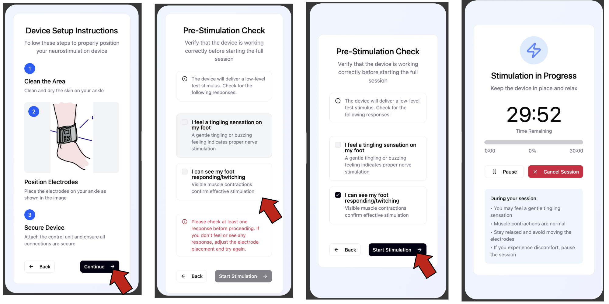
An ankle-worn stimulation prototype. I worked on circuit simulations, Arduino firmware, and electrode testing.
Read project notes →
In progress
Baja SAE — Blue Jay Racing
Engine/CVT Dyno
Our first RPM pickup read cleanly to 15,000 RPM on the bench, then proved unreliable on the car. Now I’m building a mixed-signal DAQ board for the team’s engine/CVT dyno.
Read project notes →
Earlier work
Layout only
USC ACME Lab · Jun 2024 – May 2025
Microwave Field Probe PCB
Schematic entry and PCB layout for a compact 1.7 GHz microwave field probe.
Read project notes →
Research — JHU IMERSE Lab
Surgical Pedal Interface
Role
Interface PCB and ESP32-to-ROS2 bridge
Tools
KiCad, ESP32, ROS2, oscilloscope
Timeline
Jan 2026 – Present
Current work
Command expiration in firmware
Status
In progress
Understanding the generator
I’m building a board that lets a computer trigger an electrosurgical generator while the surgeon can still use the pedal. It also logs pedal events in ROS2.
The generator was a black box. I expected a straightforward contact closure, but the resistance readings didn’t look like a simple switch. I mapped the connections and worked out which commons needed to stay separate.
From breadboard to PCB
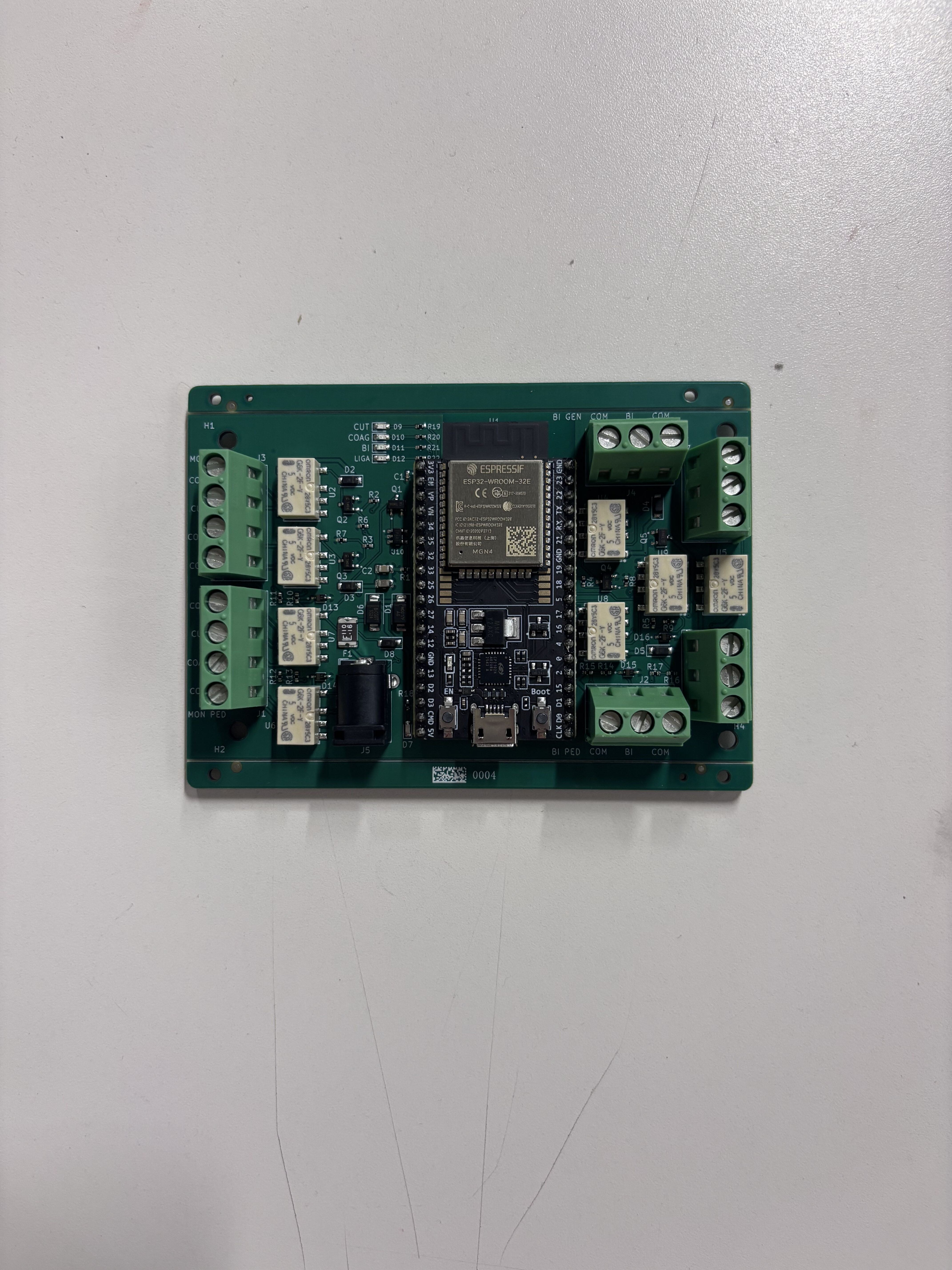
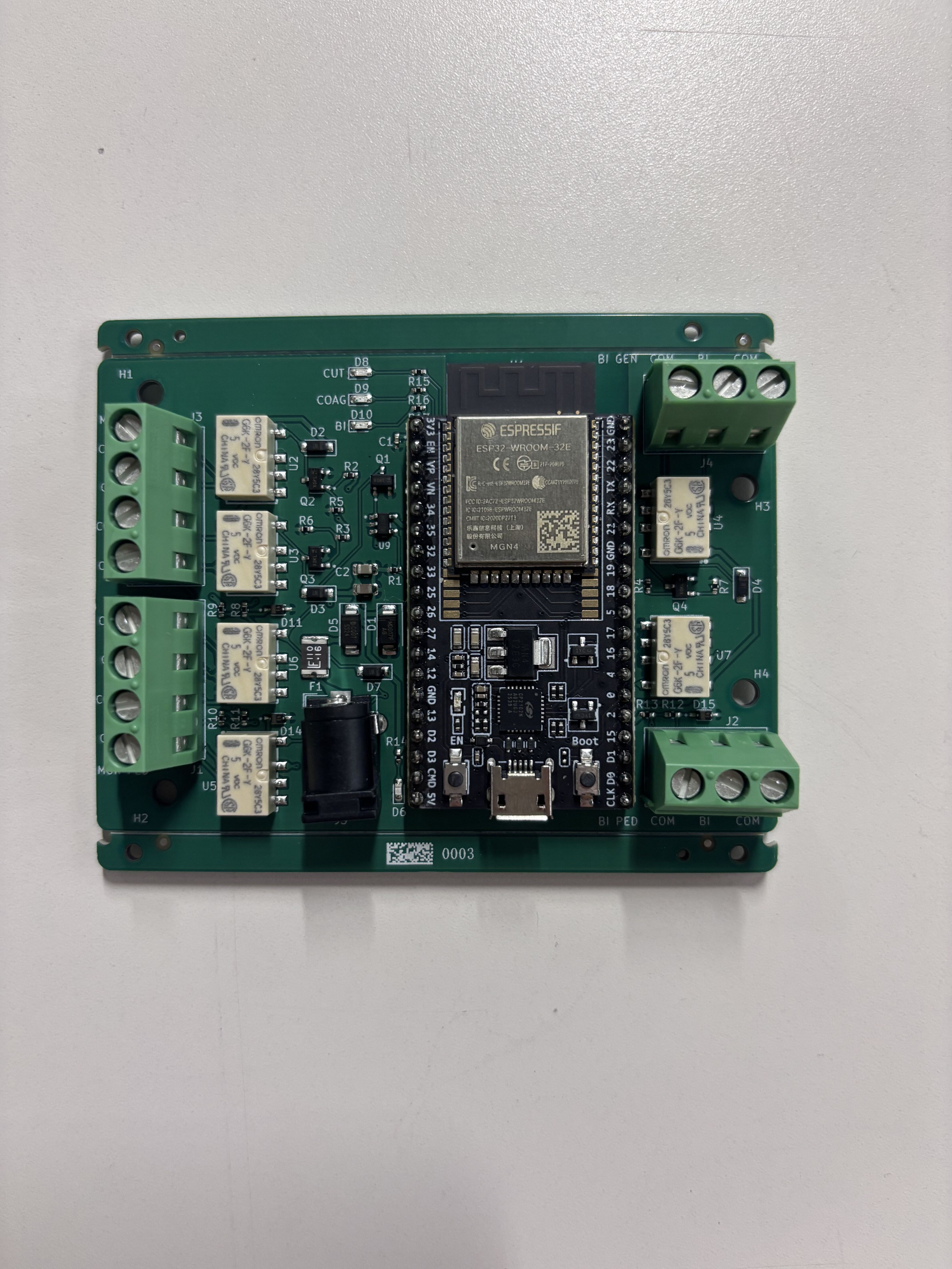
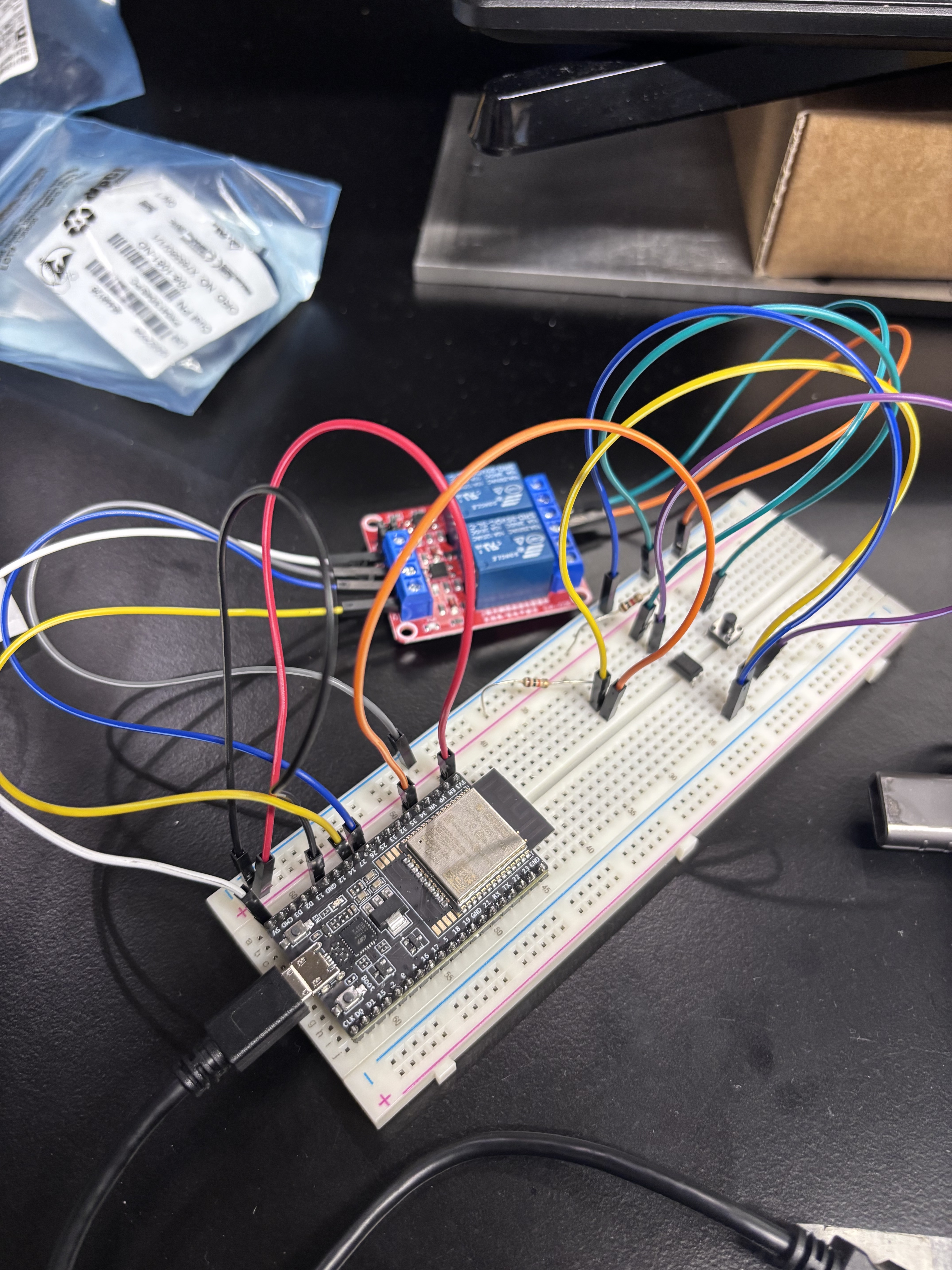
I started with an ESP32 and relays on a breadboard, then designed and assembled the PCBs shown below.
The six-relay v2 design supports CUT, COAG, and bipolar. The latest design, v3, uses eight relays and adds LigaSure.
Expand image ↗FIG. 01 — Assembled v3: CUT, COAG, bipolar, and LigaSureExpand image ↗FIG. 02 — Assembled v2: CUT, COAG, and bipolarExpand image ↗FIG. 03 — Early breadboard setup with ESP32 and relay module
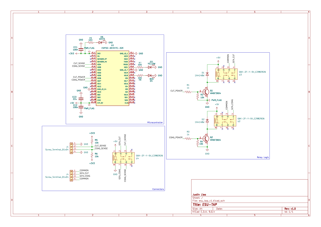
Earlier design files
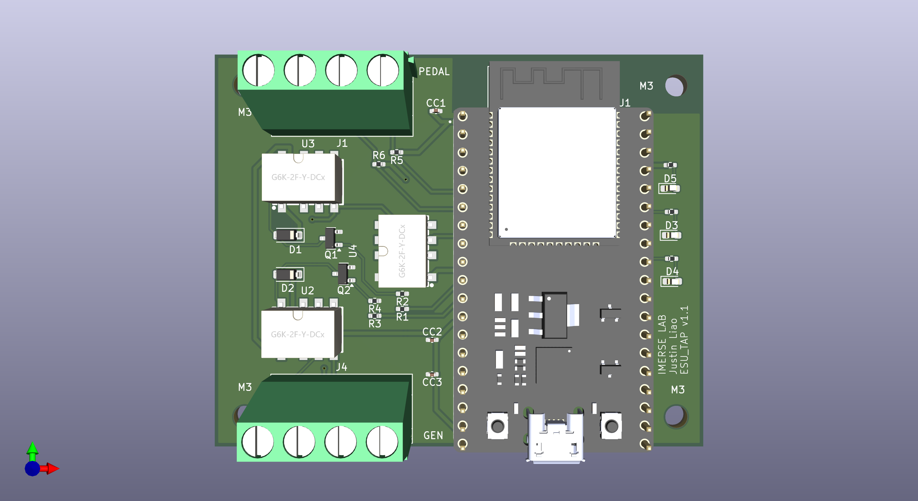
Open the earlier schematic and PCB renderExpand image ↗FIG. 04 — Earlier relay-driver schematic, v1.0Expand image ↗FIG. 05 — Earlier PCB render, v1.1
Command expiration
The watchdog monitors a firmware heartbeat to catch a hung ESP32. But if the PC application stops sending commands while the ESP32 keeps running, the last ON command can stay active. I’m adding a timeout so the application has to keep renewing that command.
KiCadESP32ROS2Relays
Research — USC ACME Lab
Microwave Field Probe PCB
Role
Schematic entry, miniaturization, and PCB layout
Tools
KiCad, STM32-based design
Timeline
Jun 2024 – May 2025
Status
Layout only
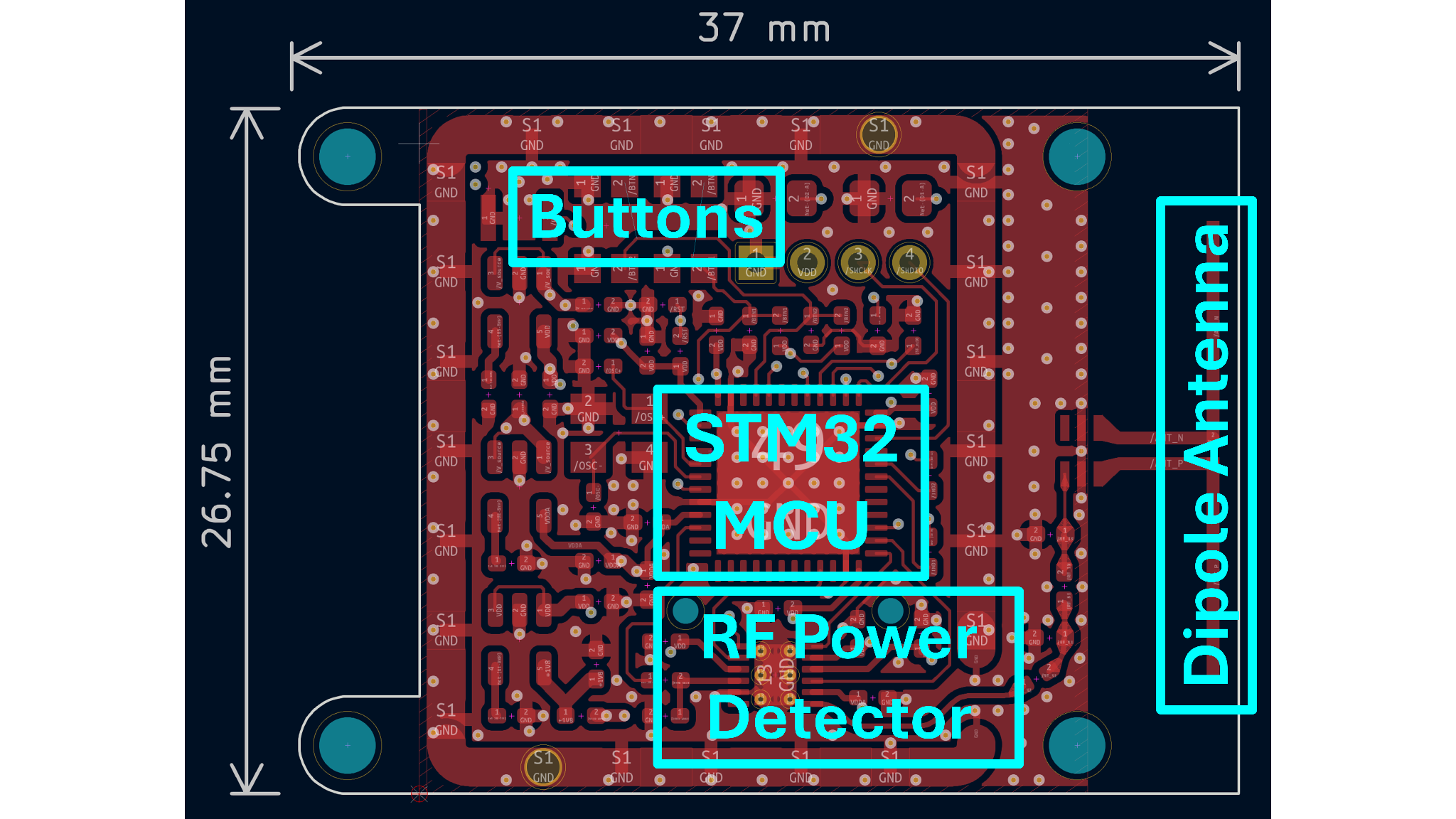
PCB layout
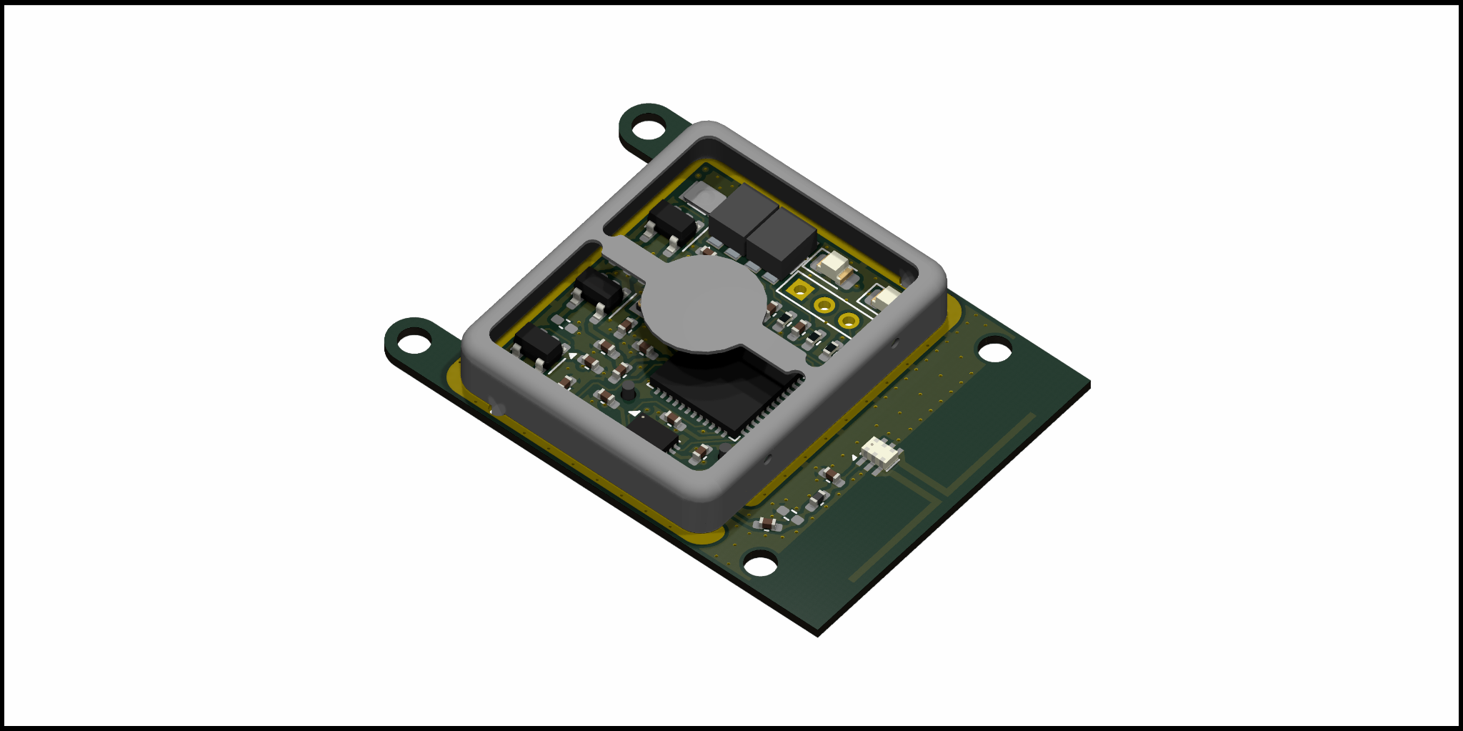
Spyglass Mini was a compact probe for a 1.7 GHz microwave cavity. A PhD researcher designed the circuit and handled the calculations. I entered the schematic and laid out the PCB, working to make the board smaller.
This was my introduction to impedance matching and RF shielding in PCB layout.
Expand image ↗FIG. 01 — Annotated layout showing the antenna, detector, and MCU
The board
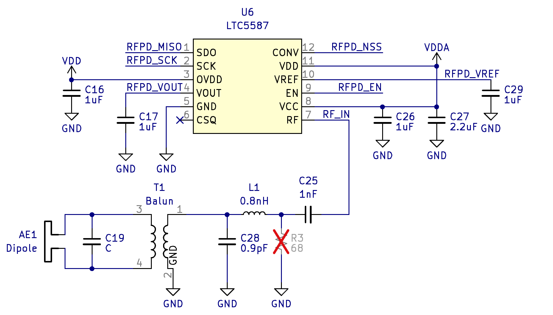
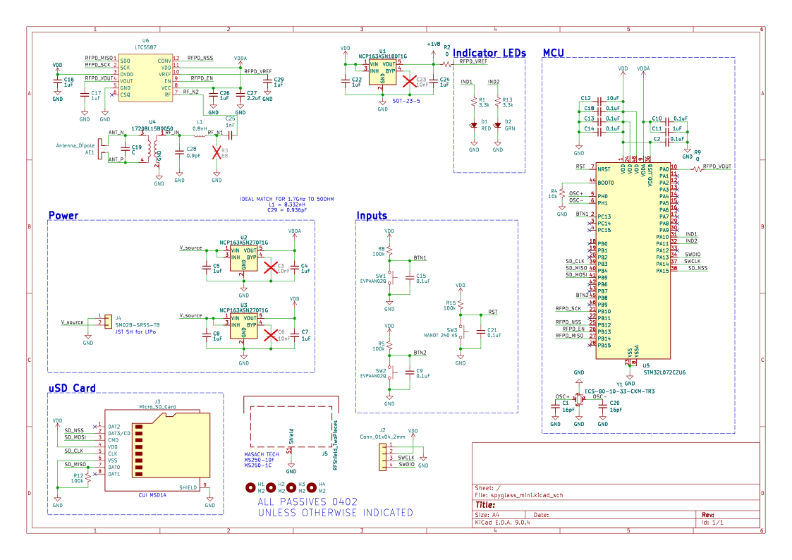
The board combines a dipole antenna, balun and matching network, power detector, and STM32 with SD storage.
Expand image ↗FIG. 02 — Antenna, balun, and detector input networkExpand image ↗FIG. 03 — PCB render (KiCad 3D)Open the full schematicExpand image ↗FIG. 04 — Full system schematic
Sampling requirements
The original specification was roughly 1 MSps with SD logging and a six-hour battery target. We later learned the application needed roughly 100 MSps. The lab pursued a different design for that requirement, and this board was never fabricated.
KiCadPCB LayoutRF
Research — USC ACME Lab
EPR Positioning Stage
Role
Stage integration, controller PCB, and PC controls
Tools
KiCad, RP2040, TMC2209, NEMA 17
Timeline
Jun 2024 – May 2025
Result
±0.03 mm in 10 of 10 trials
Status
Built & tested
Positioning the spectrometer
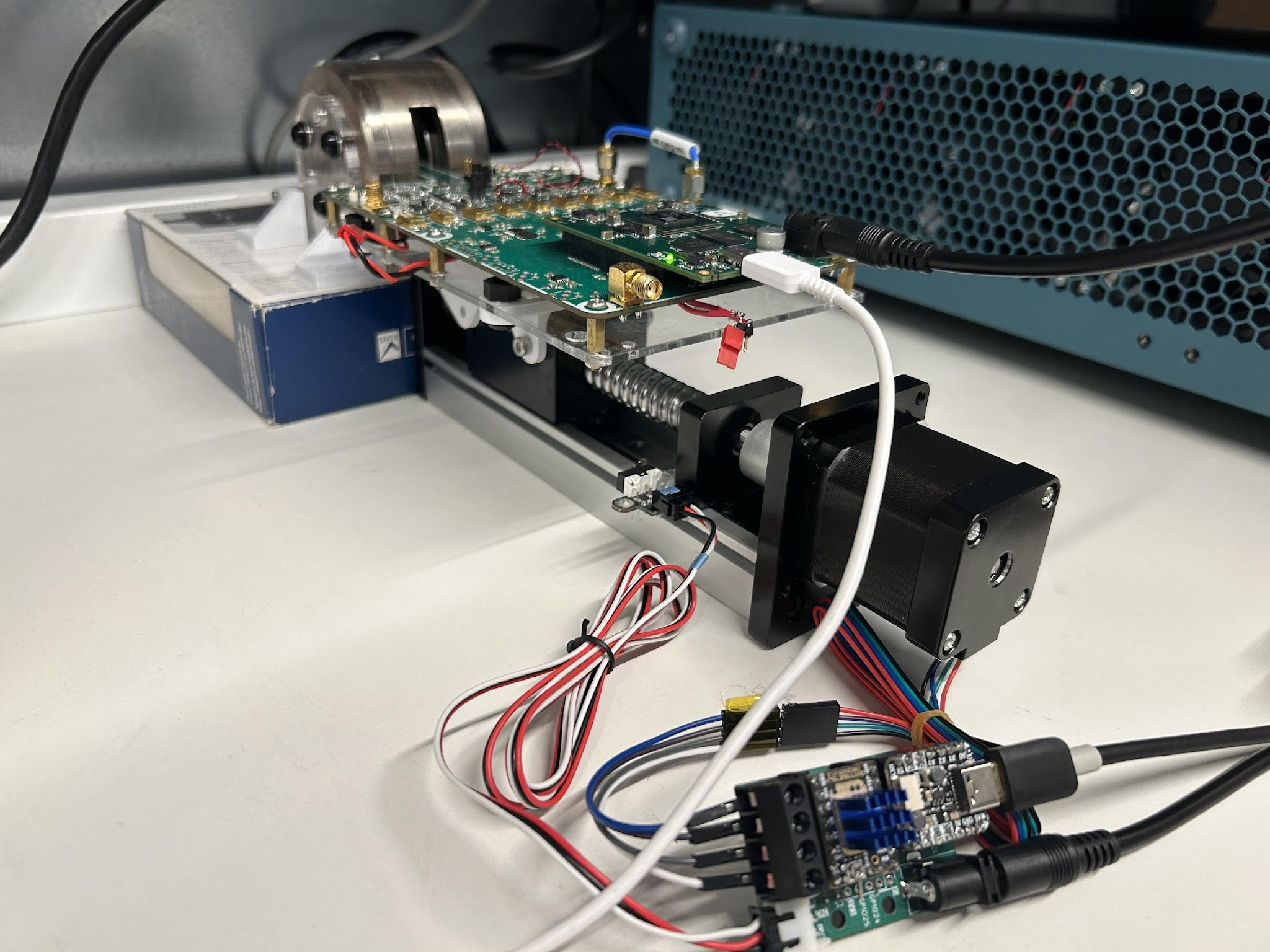
The lab needed to move a miniaturized electron paramagnetic resonance spectrometer into a magnet’s uniform-field region. I built a USB-controlled stage around a ball-screw rail and stepper motor, with a custom controller PCB and PC controls.
Expand image ↗FIG. 01 — Spectrometer on the stage; controller in the foreground
Homing
The stage needed to start from the same place every time. I used a limit switch to set the home position before each move, then checked where the stage landed.
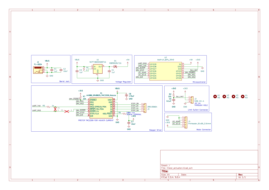
The controller uses an RP2040-based board and a TMC2209 driver for the NEMA 17 stepper. The PC software handles USB commands for homing and movement.
Expand image ↗FIG. 02 — RP2040 controller and TMC2209 motor driverExpand image ↗FIG. 03 — Controller schematic (KiCad)
Position measurements
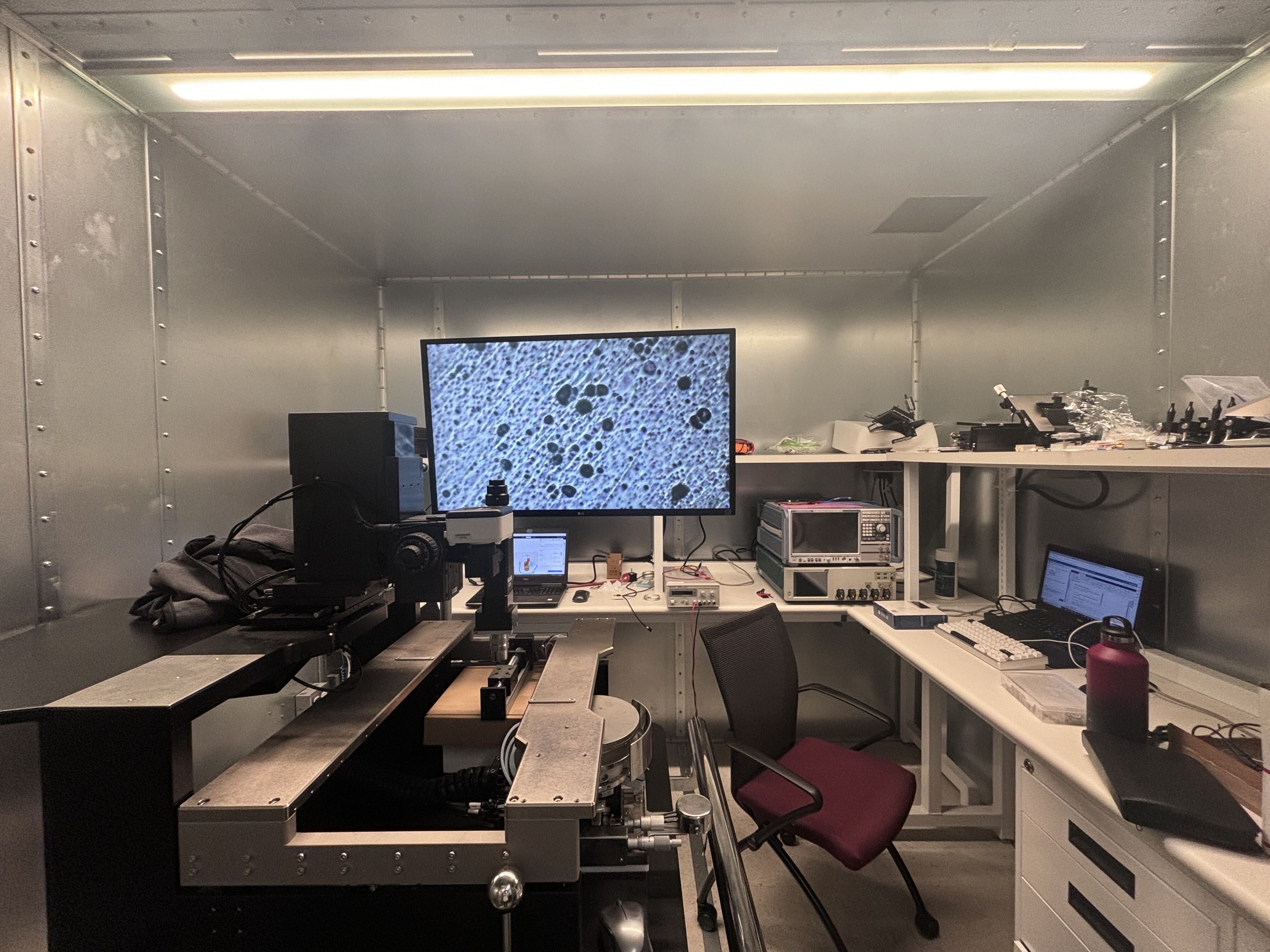
I ran 10 trials: home the stage, command a move to the target, and check where it landed under the lab’s inspection microscope. All 10 landed within ±0.03 mm, read off the microscope’s scale. The field of view was so narrow that about two extra motor steps would have pushed the target off the screen, so a miss would have been obvious.
Expand image ↗FIG. 04 — Lab inspection setup used for visual position checks
KiCadRP2040Stepper Control
Biomedical — JHU Design Team
PelviStim Wearable Prototype
Role
Circuit simulation, Arduino firmware, and hardware testing
Tools
LTspice, Arduino Mega, Bluetooth, NeuroStimDuino
Timeline
Oct 2025 – May 2026
Evaluation
7-person electrode comparison; separate 5-person setup test
Status
Prototype tested
Circuit development
PelviStim was our team’s ankle-worn stimulation project. My circuit work focused on the op-amp supply rails and a DC–DC converter for the higher-voltage output.
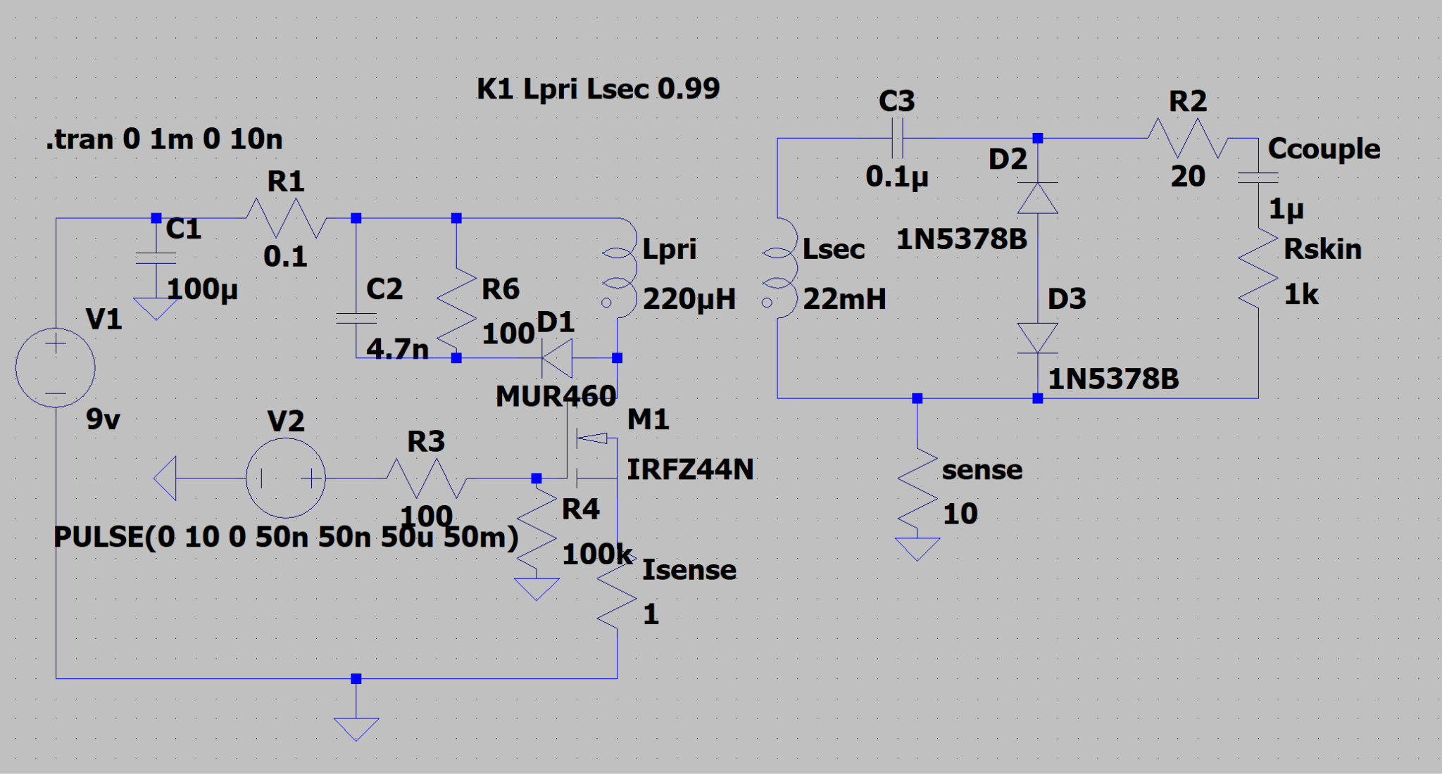
In LTspice, I worked on the converter and a separate voltage-to-current circuit. The converter rang, and its output wasn’t current-controlled yet. The current pump held about 22 mA from 500 Ω to 1.5 kΩ. At 3 kΩ, that current would require 66 V across the load, beyond the circuit’s ±48 V rails; simulated output reached about 16 mA.
Expand image ↗FIG. 01 — Early converter simulation with a resistive load model
Hardware and firmware
While the custom circuit was still in simulation, we tested hardware with a NeuroStimDuino shield on an Arduino Mega. I set up and characterized its output with an oscilloscope and helped with electrode/contact impedance testing.
I made the Arduino communicate over Bluetooth and handle incoming commands. My teammate handled the phone app. During integration, we found that the two sides were using different command formats.
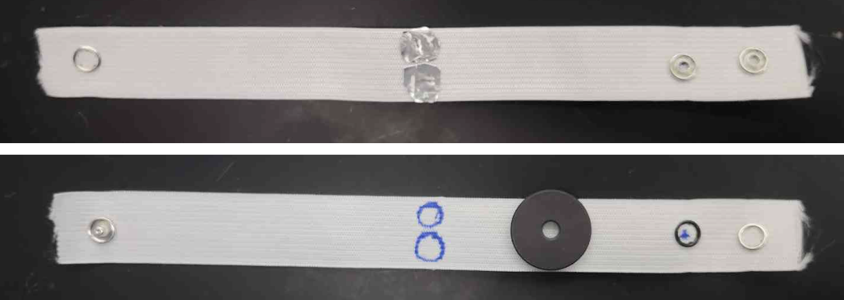
Expand image ↗FIG. 02 — The team’s electrode-band prototype
Electrode comparison
I documented a seven-person comparison of the prototype electrodes with TENS/gel pads, using NeuroStimDuino and an oscilloscope. We recorded the current and voltage at each participant’s reported sensation threshold.
Both electrode types tested with the same seven participants
Electrode
Mean recorded current at sensation threshold
Prototype
7.43 mA
TENS/gel comparison pads
10.86 mA
The prototype electrodes reached sensation threshold at lower current but needed higher voltage, making voltage headroom a concern for the custom circuit.
Setup testing
In the team’s five-person usability test, everyone reached the ready-to-start point within 15 minutes. Three were team members; two had never seen the device. The test used the wearable with an off-the-shelf Bluetooth stimulator and ended before a treatment session.
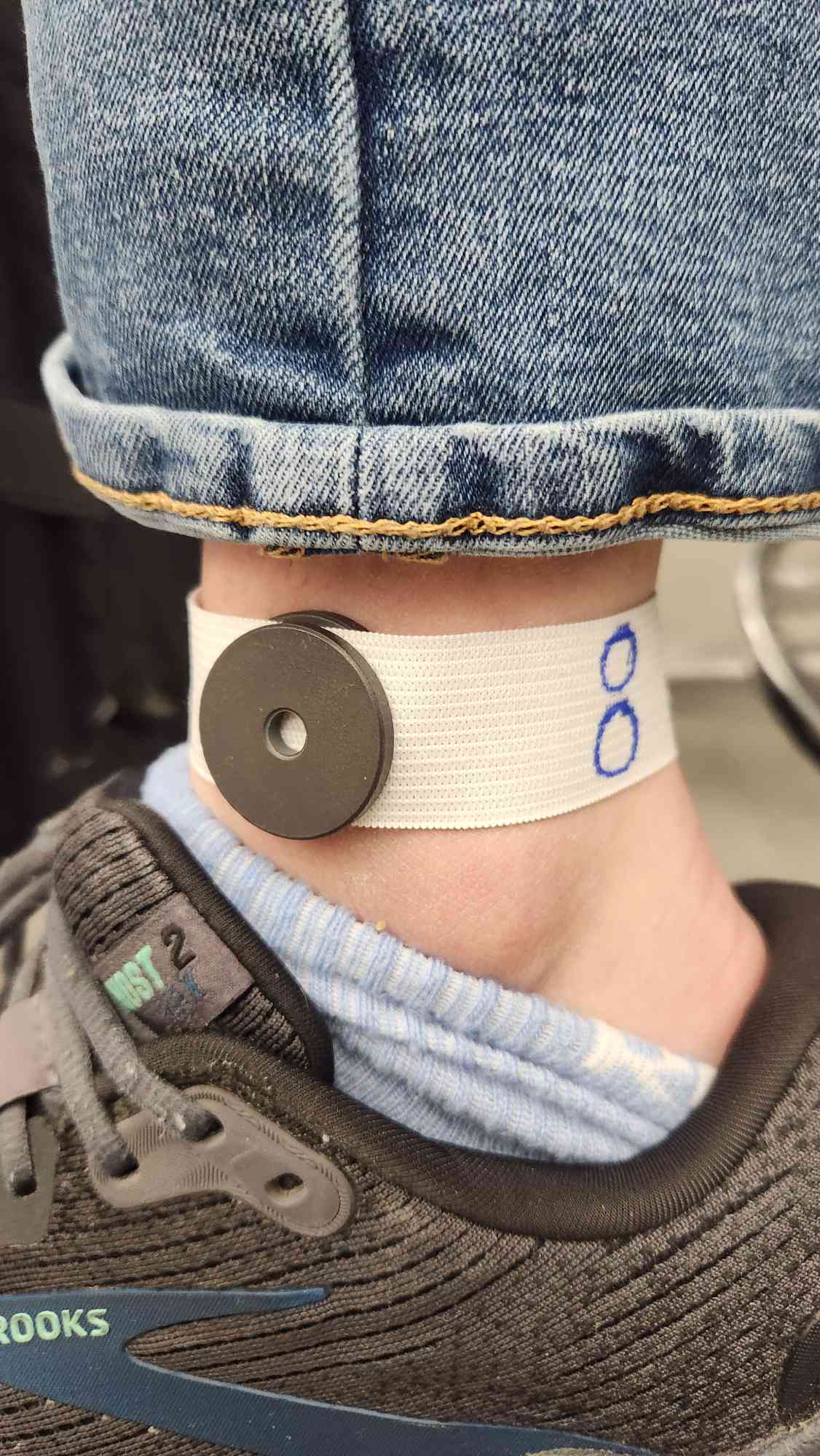
The two new users struggled with placement, getting orientation and contact wrong until observers flagged it. That led to clearer placement instructions in the app.
Expand image ↗FIG. 03 — Electrode band worn at the ankleExpand image ↗FIG. 04 — Companion app screens developed by teammates
LTspiceArduinoBluetoothPrototype Testing
Baja SAE — Blue Jay Racing
Engine/CVT Dyno
Role
Sensor characterization, dyno calculations, and DAQ PCB
Tools
KiCad, Teensy 4.1, oscilloscope, DMM
Timeline
Aug 2025 – Present
Bench result
Earlier perfboard RPM prototype tested to 15,000 RPM
Status
In progress
Measuring engine and CVT performance
We’re building a dyno to measure engine power and CVT efficiency across the RPM range so we can tune the drivetrain. I’m working on the data-acquisition board and the calculations for the two transducers.
The bench result didn’t carry over
Our earlier perfboard RPM pickup read cleanly on the bench up to 15,000 RPM. On the car, the spark-plug pickup was too inconsistent to rely on. In separate tests of the two torque transducers, I found that one had failed.
The mixed-signal board
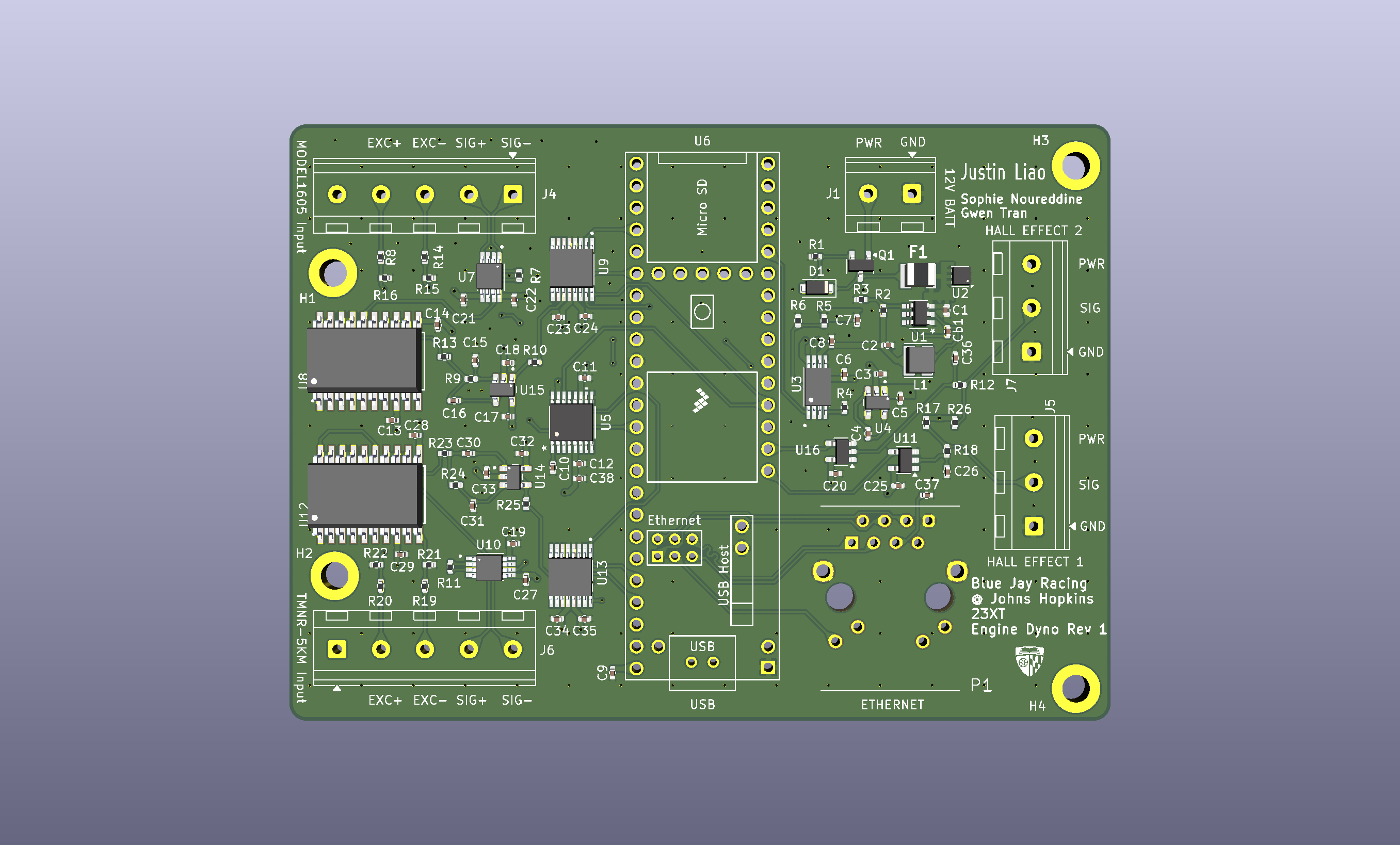
I’m designing a four-layer DAQ board around a Teensy 4.1. The main challenge is keeping small analog sensor signals clean next to digital lines and power circuitry. I also plan to add Ethernet telemetry.
I'm studying electrical and biomedical engineering at Johns Hopkins,
with a minor in robotics. In the IMERSE Lab, I work on a pedal interface
for robotic-surgery research and have collected microrobot motion data
for imitation learning. I also develop drivetrain data-acquisition
electronics for Blue Jay Racing.
Experience
Research Assistant
IMERSE Lab — Johns Hopkins University
Jan 2026 – Present
Electronics & Firmware Team Member
PelviStim Design Team — Johns Hopkins University
Oct 2025 – May 2026
Data Acquisition Team Member
Blue Jay Racing, Baja SAE — Johns Hopkins University